
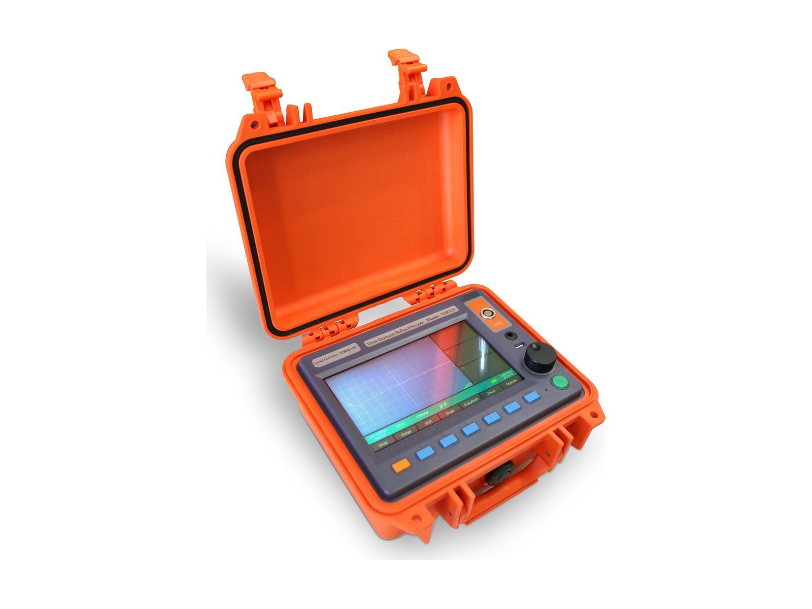
Fault location instruments, in the order you use them.
Grouped by the step they do, from the first pulse to the dig spot.
Show
Step 1: Pre-location
Measure the distance to the fault.
A low-voltage pulse goes into the cable. The time its reflection takes to come back gives the distance to the fault.
Step 1, pre-locate
ARM Filter
Arc reflection filter
- Method
- Arc reflection (ARM)
- Works with
- TDR-901, PG-32
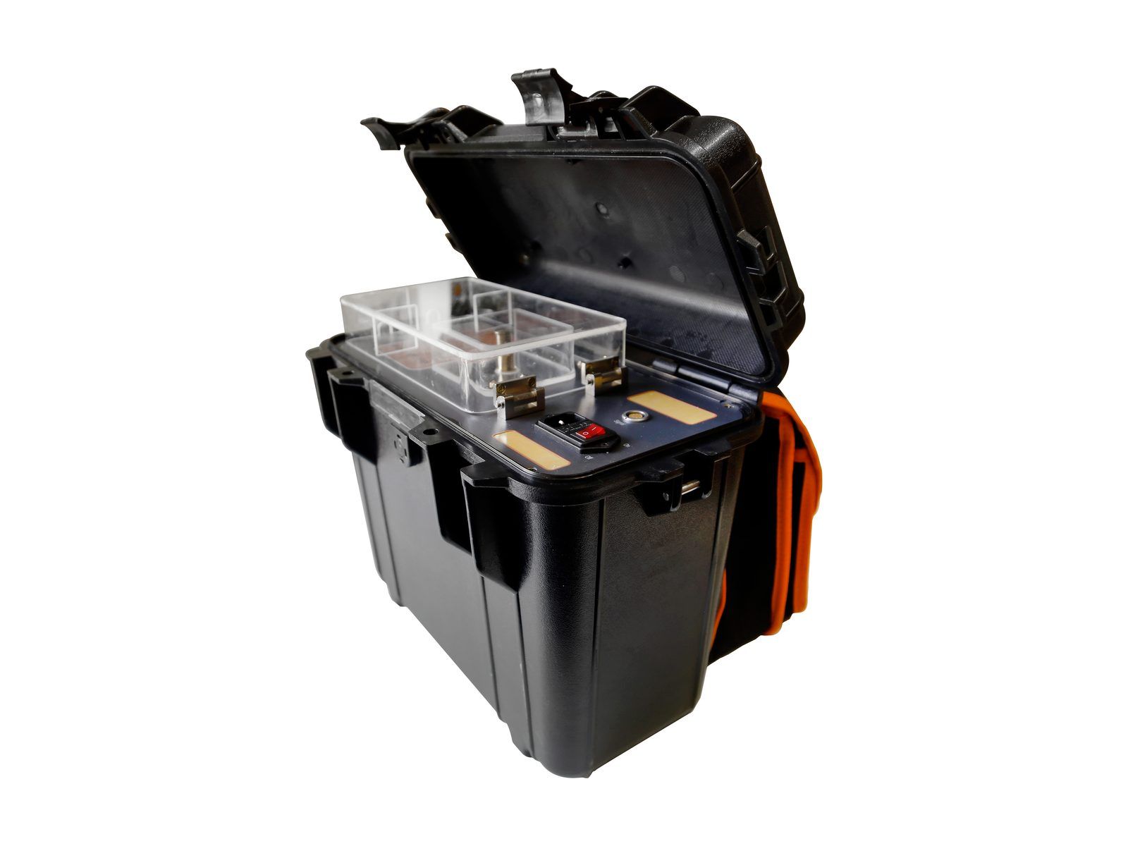
Step 2: Surge & conditioning
Break the fault down so it can be found.
A high-voltage surge breaks down high-resistance and intermittent faults, so they reflect clearly and flash over audibly.
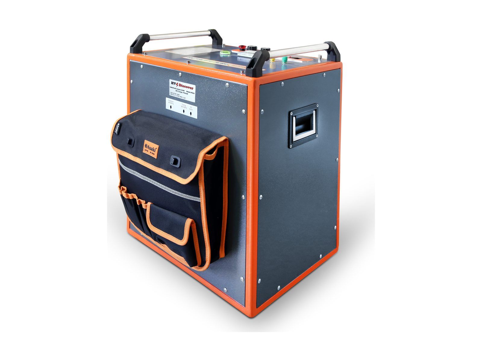
Step 3: Pinpointing
Find the exact spot to dig.
Walk the route while the surge generator fires and listen for the discharge through the ground. The loudest point is where you dig.
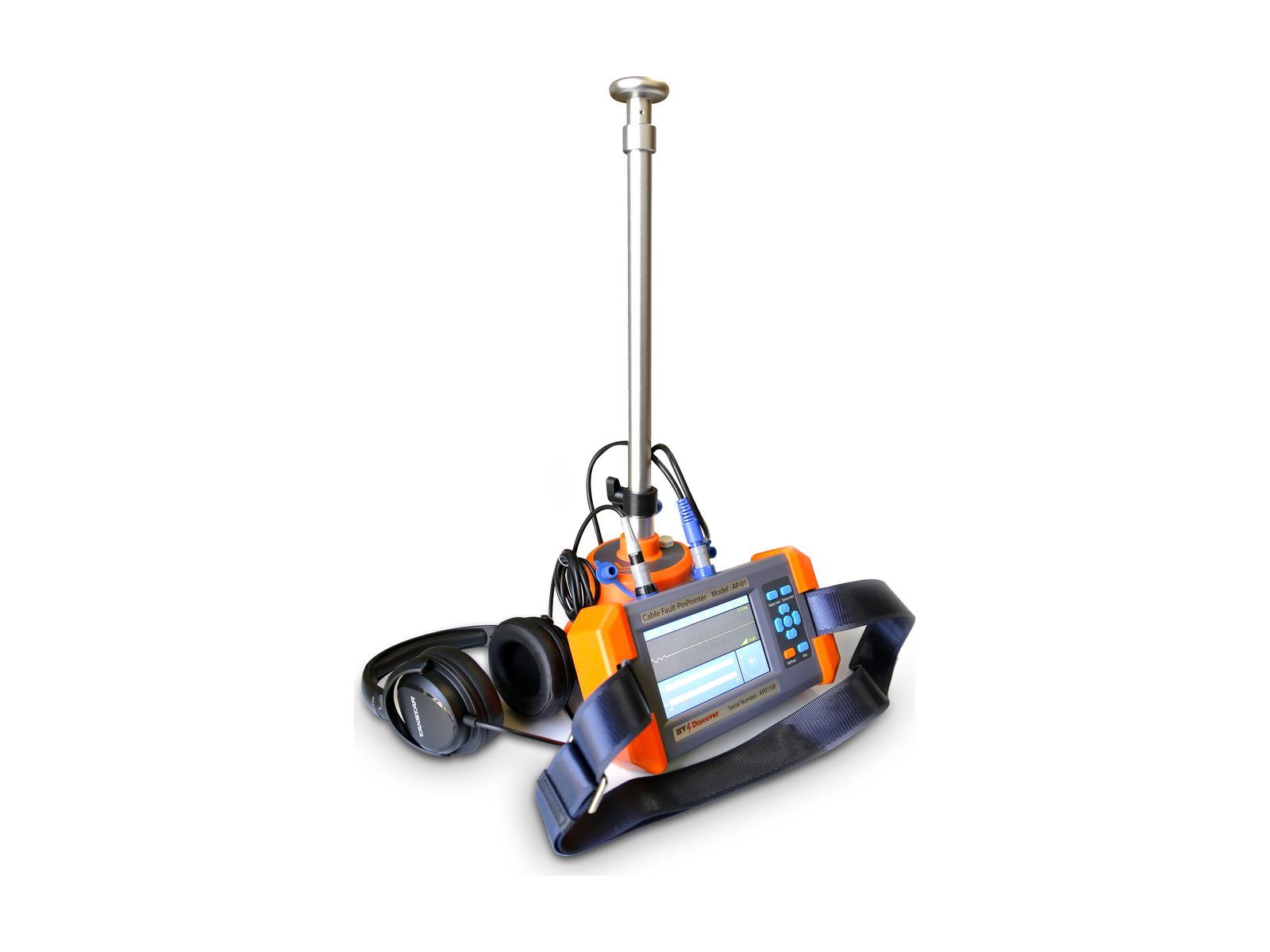
Step 4: Route tracing
Follow the cable path.
A transmitter puts a signal on the cable and a receiver follows it, so the measured distance lands on the right street.
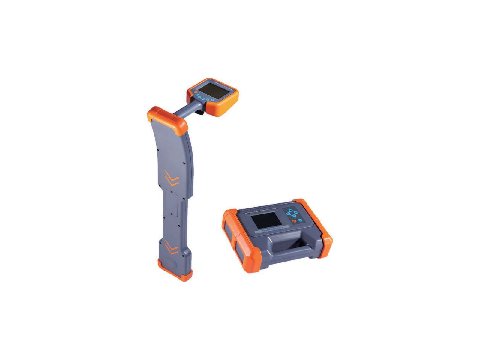
Step 4, trace route
CRT-015
Cable route tracer
- Set
- Receiver and transmitter
- Works with
- TDR-901, AP-01
Steps 1 to 4: Integrated system
All four steps, fitted in one vehicle.
Reflectometer, surge generator, pinpointer and route tracer, wired in and ready when the van arrives.
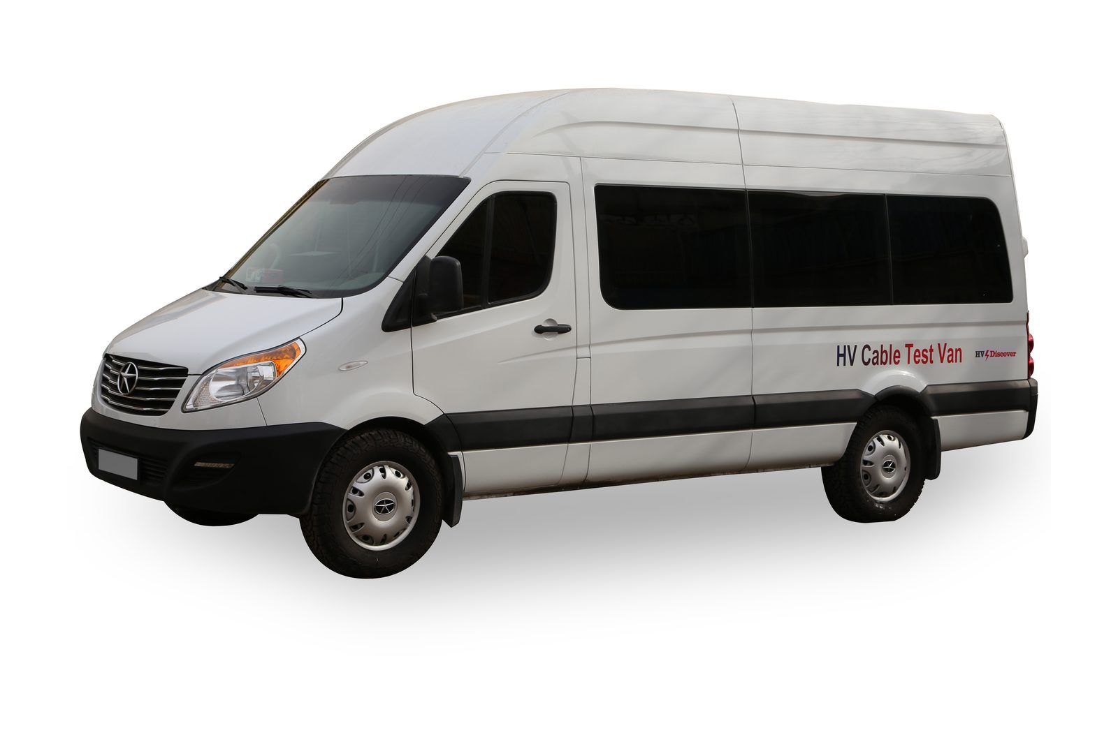
Steps 1 to 4, integrated
Cable test van
Vehicle-mounted cable fault locating system
- Steps covered
- 1 to 4
- On board
- Reflectometer, surge generator, acoustic receiver, route tracer
- Body
- High-roof panel van
Not sure which instruments you need?
Tell us the cable voltage, the length and what the fault is doing. We’ll recommend the set.