
Integrated system: steps 1 to 4
The whole fault-location chain, in one van.
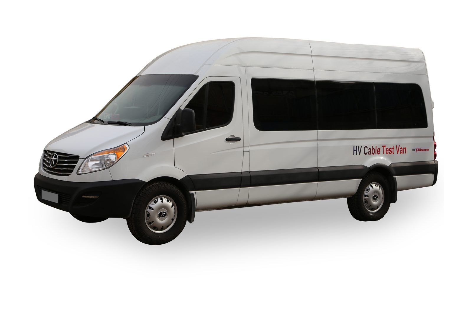
Cable test van Vehicle-mounted cable fault locating system
Reflectometer, surge generator, acoustic receiver and route tracer on board, wired to a control panel and to a high-voltage connection panel at the rear doors. The crew arrives ready to measure.
- Steps covered
- 1 to 4
- On board
- Reflectometer, surge generator, acoustic receiver, route tracer
- Body
- High-roof panel van
- At the rear
- HV connection panel, four cable reels
What’s on board
One instrument set for each step of the sequence, and what each one does once the van is parked.
-
Step 1: Pre-locate
Reflectometer
On the bench, in an orange hard case.
In the van: takes the first shot from the bench, and the arc reflection shot once the surge is running.
-
Step 2: Condition
Surge generator
With the HV connection panel at the rear doors.
In the van: charges the cable through the rear connection panel and keeps firing on its timer while the crew walks.
-
Step 3: Pinpoint
Acoustic receiver
With headphones.
In the van: leaves with the crew. They walk the route with the ground sensor and listen for each surge.
-
Step 4: Trace route
Route tracer
Transmitter and receiver.
In the van: marks the cable route at the surface, so the distance is walked along the real path.
Also on board: a control panel with meters and status lamps and a UPS in the cabin, and at the rear doors the high-voltage connection panel and four cable reels.
Inside the cabin
The working side of the van: instruments on the bench, the control panel beside them, the UPS below.
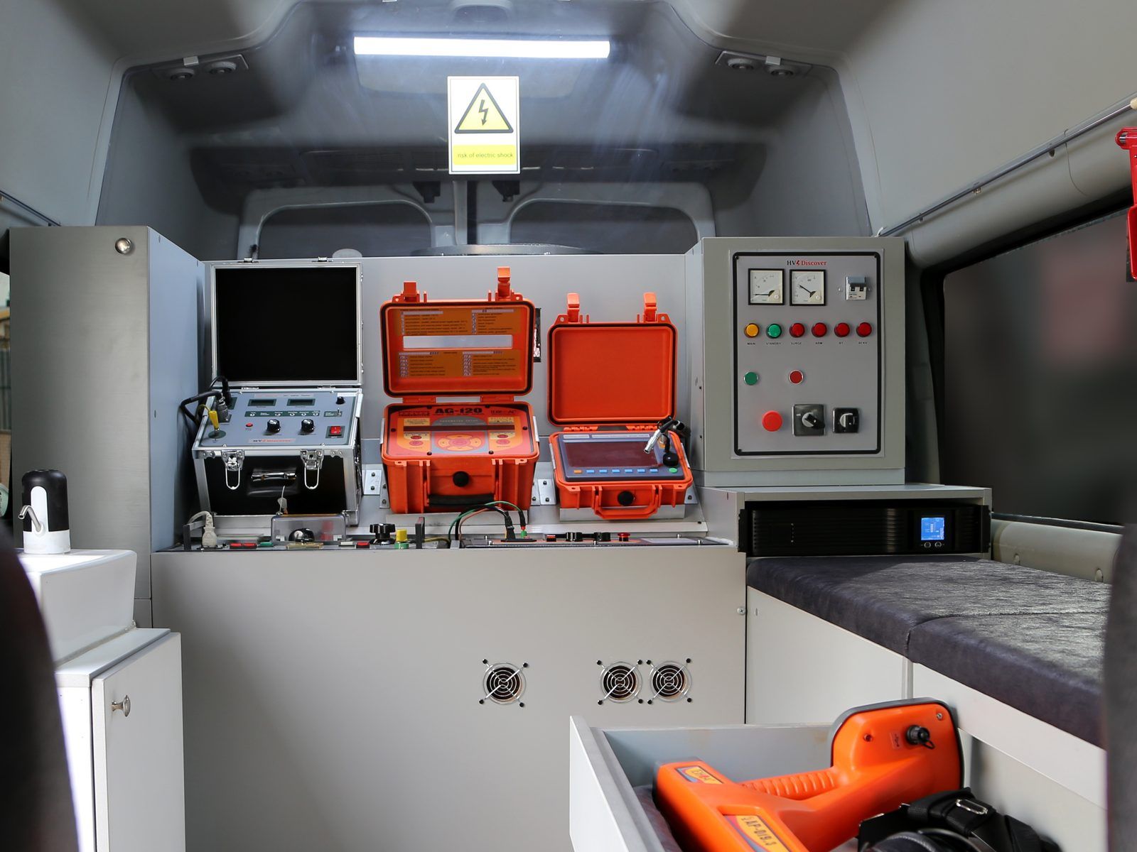
- 1. Instrument in an aluminium case HV Discover label, two digital displays and a high-voltage lead.
- 2. Route-tracing transmitter In an orange hard case.
- 3. Reflectometer Step 1, in an orange hard case on the bench, ready for the first shot.
- 4. Control panel Two meters, status lamps for main, standby, surge, ARM, BT and 80 kV, a red push button and selector switches.
- 5. UPS Under the control panel.
- 6. Pull-out drawer A hand-held receiver and headphones.
Items 1 to 3 are identified from the photo only.
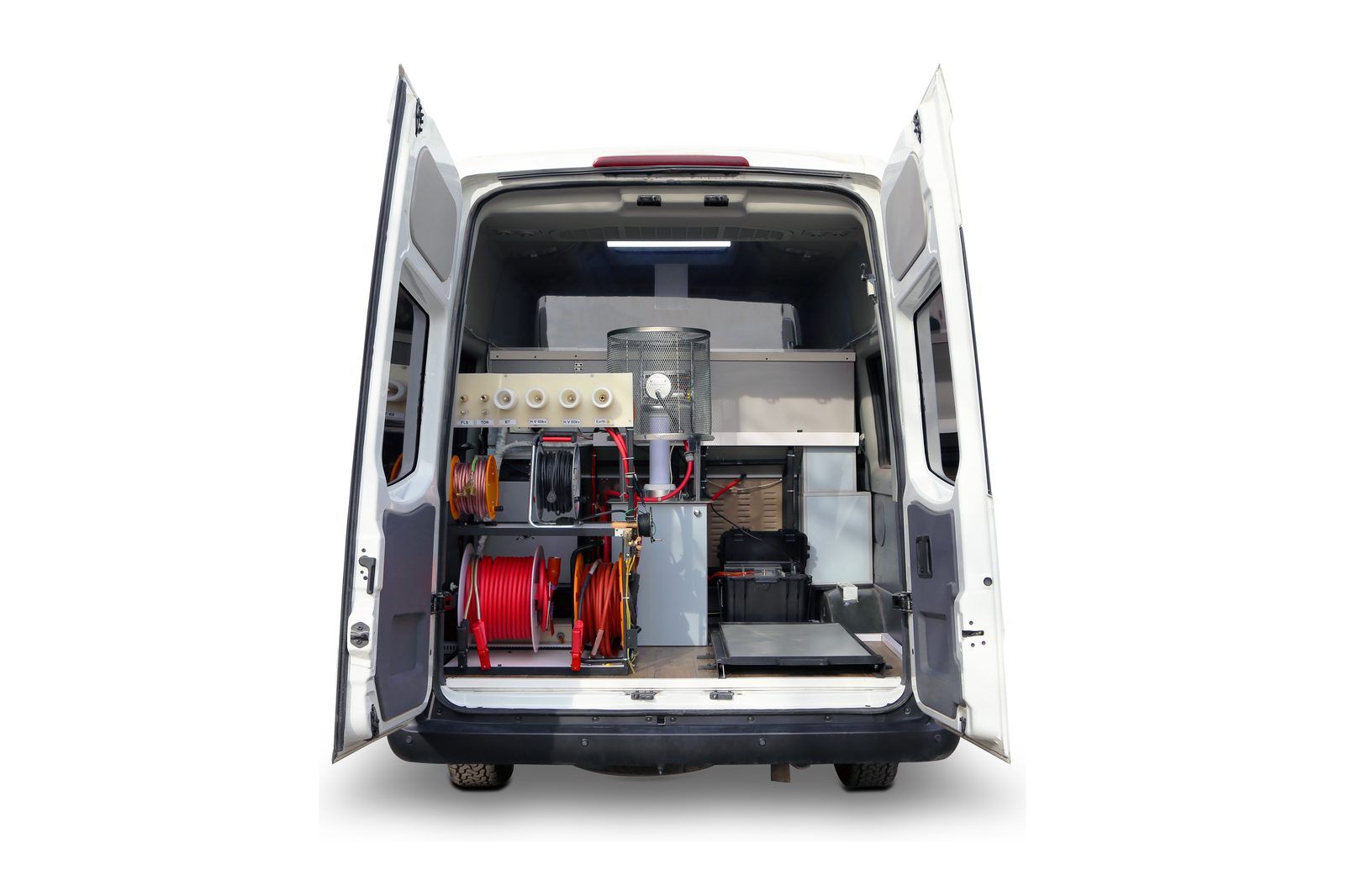
At the rear doors
The high-voltage side opens at the back, away from the crew’s seats.
- Connection panel with terminals labelled TDR, FLS, BT, H.V 40 kV, H.V 80 kV and Earth.
- Output cable reels, red and orange.
- A unit inside a mesh guard, wired to the panel.
- Instrument cases and a pull-out tray
Photos
The van from each side, with the side and rear doors open, and two views inside the cabin.
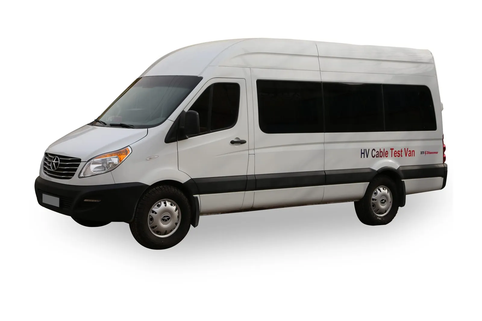
Front three-quarter view.
How a call-out works
From parking to the dig spot, with the instruments that do each part.
-
Arrive
Park at the cable end. Everything for the four steps is already on board.
-
Connect
Earth first, then run the output cable from the reel to the faulty core.
-
Pre-locate
With the reflectometerA low-voltage shot from the bench gives the distance to the fault in metres.
-
Surge
With the surge generatorA high-resistance fault is broken down; the arc reflection shot confirms the distance.
-
Pinpoint
With the route tracer and acoustic receiverTrace the route to that distance, then listen for each surge. The discharge is loudest above the fault.
-
Mark the dig spot
Mark it on the ground for the excavation crew.
Specifications
Equipment as photographed.
Instruments
| Reflectometer | On the bench, in an orange hard case |
|---|---|
| Surge generator | With the HV connection panel at the rear doors |
| Acoustic receiver | With headphones |
| Route tracer | Transmitter and receiver |
| Control panel | Two meters; lamps for main, standby, surge, ARM, BT and 80 kV, as labelled |
| UPS | Rack-mounted under the control panel |
High voltage
| Rear panel terminals | TDR, FLS, BT, H.V 40 kV, H.V 80 kV, Earth, as labelled |
|---|---|
| Cable reels | Four, at the rear doors |
Vehicle and cabin
| Body | High-roof panel van, side windows, sliding side door, twin rear doors |
|---|---|
| Instrument bench | Cooling fans in the front, pull-out drawer for the hand-held instruments |
| Lighting | LED roof light |
| Safety | Fire extinguisher bracket, electric shock warning sign |
| Hand wash | Water dispenser at the bench |
Talk to us about the van.
Questions about the equipment on board, the vehicle or how a crew works from it. We reply by email.